PiFace
Introduction

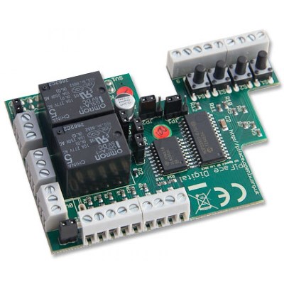
Support for the PiFace I/O board is available in release 1045 and onwards. This board supports 8 digital inputs, 8 digital outputs (open collector) of which two are equipped with relays capable of switching 5A/20V (the relays themselves have a higher rating but the circuit board and screw terminals do not).
This daughterboard slots onto the GPIO header. A total of 4 PiFace boards can be used with one Raspberry Pi. A special casing is available for a single stack of a Raspberry Pi + PiFace.
Follow this Domoticz forum thread for the latest discussion.
Robin Stevenhagen developed support software for the PiFace to be used in Domoticz. Inputs and Outputs appear as Lighting 1 devices and all in- and outputs can be defined as counter and appear as RFXMeter, making it a replacement for the RFXCOM RFXMeter which is end of life.
Installation
The PiFace driver works as follows:
- Enable the spi-bcm2708 module in /etc/modprobe.d/raspi-blacklist.conf (put a # before blacklist) or use raspi-config in the advanced options
- For newer installations of firmware for Raspberry Pi:
    sudo raspi-config
    8 Advanced Options
    A5 Device Tree -> disabled
- Reboot
- Put a piface.conf configuration file in the domoticz program folder if one is not automatically created, needed if the default config (see later on) needs to be changed.
- Select PiFace from the Setup.Hardware menu
- Goto the Setup.Devices screen and add devices..
Functions:
Inputs:
Changes (when applicable) are reported to Domoticz at 100 msec rate
Configuration options: (configurable through the piface.conf file)
- level,
- rising edge (button press)
- falling edge (button release)
- inverted level
Outputs:
The following options for output state reporting are possible, HOWEVER Domoticz does not seem to like anything else than Level, have to figure out why...
Configuration options: (configurable through the piface.conf file)
- level,
- rising edge (on output set)
- falling edge (on output reset)
- inverted level
Counters:
Can be enabled on ALL inputs and outputs.
For the inputs hardware edge detection is used, for the outputs software edge detection is used @ the input report rate. (both are rising edge)
The hardware registers are sampled every 20 msec (at least that is the intention... :? ), which should allow for 50Hz signals....
Tests @ 5Hz showed an error rate of approx 0.5- 0.7% (tested with 40000 and 185000 counts, with 50/50 and 30/70 duty cycles, tested with 3 parallel connected inputs)
Tests @ 10Hz showed an error rate of approx 3.3 - 3.7 % (avg 3.4 %) (tested with 40000 and 87000 counts, with 50/50 duty cycles)
Initial test @ 20Hz showed an error rate near 10%
The encountered errors are due to kernel / userland switches and the linux multitasking mechanism, and are the best achievable.
PiFace devices and numbering:
Enabled I/O ports will be reported as a lighting 1 (impuls) device.
The ID field will show if a pin is a input (I) or output (O).
The Unit field will show the PiFace board, and pin number. The decade number ID's the PiFace board, the unit number the pin number.
So Unit 25 = PiFace Board address 2, and pin-number 5 (pin-count starts at 0)
Enabled Counters will be reported as an RFXMeter.
The ID field will show the PiFace address, Pin-type, and Pin-number.
The hundreds tell if a pin = input or output (input = 1xx, output 0xx)
The decades = address of the PiFace board
The unit number = pin-number
Configuration file
piface.conf in the Domoticz directory defines the function of each in- and output
Lines in the piface.conf take the form of:
piface.<board address>.<I/O>.<pin number>.<parameter>=<value>
where:
- board address = 0 for first board, 1 for second board etc.
- I/O= I for input, O for output
- pin number=0 for fist pin ~7 for last pin
- parameter =
- enabled=0 | 1 | true | false
- pin_type= level | inv_level | rising | falling
- count_enabled = 0 | 1 | true | false
- count_update_interval_sec = 0..3600 (seconds)
Example 1:
piface.0.input.1.enabled=true
piface.0.input.1.pin_type=falling
piface.0.input.1.count_enabled=true
piface.0.input.1.count_update_interval_sec=10
These statements would set PiFace board 0 pin 1 (which is the second pin) to be an enabled input which gets set when the input falls from hi to lo. This input also shows up as a counter (RFXmeter type) and will be updated to Domoticz every 10 seconds.
Example 2:
piface.1.output.0.enabled=true
piface.1.output.0.pin_type=level
piface.1.output.0.count_enabled=false
piface.1.output.0.count_update_interval_sec=10
This will enable the first output of the second PiFace board.
Notes
1) For the time being only use pin_type “level” for outputs
2) Changes in piface.conf only become active upon restart of Domoticz
3) Pins not defined in piface.conf will not be enabled
Defaults
The default configuration (without a piface.conf):
Input 0-3 (the buttons) enabled, with rising edge toggle (button press), counters disabled
Input 4-7 disabled, counters enabled with 10 seconds update time
Outputs 0-7 enabled, with level, counters enabled with 10 seconds update time
In all cases the pull up resistors are enabled.
All can be changed with the piface.conf (a basic version for address 0 is included in r1045).
Applications
General notes
The Inputs are connected to the GPIO pins of the MCP23S17 through a 330 Ohm resistor. The maximum voltage on the input pins is related to the 3.3V supply voltage (Vss) of the MCP23S17. An input will be considered Inactive at >0.8*Vss=2.64V and Active on <0.2*Vss=0.66V. But the maximum voltage on the input CANNOT exceed 3.9V. This makes the inputs a vulnerable part of this board and it is advised to use opto-couplers on the inputs or use the Mosfet from the S0 application below.
The Outputs are much more robust through the use of an ULN2803A darlington transistor array with built-in clamping diodes. A maximum of 50V and 500mA can be switched.
Connecting the S0 bus
With a small circuit the S0 bus of your smartmeter can be connected to the PiFace input.
With this circuit the PiFace inputs can be made much more robust, and can also be used for other I/O applications.
When using the 2N7000 this circuit can handle max 40V dc as input voltage, instead of the max 3v9 for the barefoot PiFace...
For the S0 application the 1K resistors are needed, but for other applications they can be changed to higher values like 10k or 100k to reduce input current.
Power meter rotary disc sensor

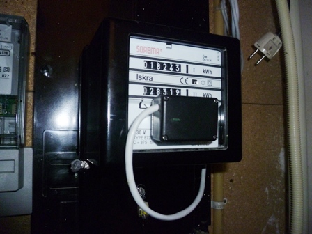
Old style power meters use a spinning rotary disc. By sensing the black part on this disc with a photo sensor a count can be generated. Fed into a PiFace input enables us to monitor power usage in Domoticz.
Although an intelligent power meter with S0 output can be obtained for no more than € 40, this project is not only cheaper but will amuse you on a rainy sunday afternoon.
It appeared the CNY70 is well suited for this purpose so i designed a circuit around it to have a proper pulse output which matches the PiFace's input. The circuit drains about 80mA and is supplied from the Raspberry Pi. It is quite much but the Raspberry Pi doesn't complain. yet.
Schematic Diagram
The whole circuit is put in a small pvc enclosure with the CNY70 sticking out and glued on the meter with double sided adhesive tape. The potmeter can be used to adjust the input level and have a single pulse per revolution. The LED will light up when the black part of the disc comes along.
Built and enclosed
CNY70 sensor sticks out
Sensor glued to power meter
Registered power usage over a week
Water meter sensor
Function

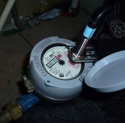
Analog water meters are equipped with a x0.0001 m3 dial which makes one revolution per liter. On top of this dial a half moon iron disc is attached. By sensing the revolutions of this disc and counting them the water flow can be logged in Domoticz.
This solution uses a proximity sensor available through dx.com described as K1208065 Metal Detection Sensor Module for Arduino at just USD 7,99. It has 3 wires: Brown (+12V), Blue (ground) and black. The black wire connects to ground when metal is detected within a range of 4mm from the sensor. Also a LED at the rear of the sensor will light up. Check the documentation on the device itself because the information at the dx.com website is different (and wrong) at the time of writing.
Mechanical
To mount the sensor firmly to the meter a large hose clamp can be used which fits around the meter. The sensor is mounted on a curtain rail wall mount with a 12mm hole drilled into it, this leaves the other dials readable for the water company. Play around a bit to find the best position for the sensor.
Electrical
As described above the PiFace inputs need some protection from the 12V used to supply the sensor. This 12V is derived from a wall plug supply. A small circuit provides this. When metal is near the sensor the relay will be switched and the contact pulls the input to ground. Without metal the switch is opened and the input will be high. A 12V reed relay like the SIL121A7272L can be used. When using a relay it could be possible that multiple counts are detected on a single event. However, so far this has not been observed.
Domoticz
In Domoticz define an input as counter by adding these lines to the piface.conf file found in the /domoticz directory.
piface.0.input.3.enabled=false
piface.0.input.3.pin_type=level
piface.0.input.3.count_enabled=true
piface.0.input.3.count_update_interval_sec=60
In this example the fourth input (input number 3) is configured as counter which reports its value to Domoticz once a minute. Restart Domoticz when the piface.conf file has been changed. Once the counter has reported its first counts an unknown device will appear in the device list. Assign a name and use the type "Water". Configure the RFXMeter/Couter setup value of Water to 1000 (pulses per cubic meter) in Application setup.
Additional reading
- Stephen Visser: Working with PiFace Blog on PiFace internal workings.
- Datasheet MCP23S17: Input circuit.
- Datasheet ULN2803A: Output circuit.