Creasol Dombus
Creasol DomBus
DomBus is a RS485 protocol developed to connect one or more DomBus devices through a RS485 serial bus, 115200bps, developed by Creasol , an italian company producing devices for the home automation.
Short video presenting DomBus products
RS485 is a serial balanced bus (using 2 wires) that permits to reliably reach 1km of distance: using a cheap 4 wires shielded cable it's possible to carry data and 12V battery-backupped power supply to all devices.
The protocol was developed with simplicity in mind: just extract the archive in the Domoticz directory, restart Domoticz and you can find the Creasol DomBus hardware in the Setup -> Hardware menu.
Use an available serial port, or connect a cheap USB-RS485 adapter, enable Creasol DomBus protocol in the Domoticz hardware panel, and connect a Creasol DomBus device to the bus: the Switches panel will be automatically populated with the inputs/outputs ports available in the DomBus device.
Any input/output that can be configured with different functions (e.g. as dimmer, low power relay, distance sensor, analog input, status led, ...), can be configured simply from the Switch panel, changing its description: for example setting description to "DIMMER" sets that output as a dimmer (to control led strips, for example). https://www.creasol.it/domotics
Features
- Wired network has several advantages over wireless systems: no interference, no RF pollution, no batteries, and works even in case of blackout.
- RS485 bus: 4 wires for both data and power supply in a thin and cheap shielded cable (normally used by alarm systems), much easier to use than LAN cable.
- When a module or a bus is supplied, their inputs and outputs will be consistent with Domoticz in only 5 seconds.
- Domoticz plugin will transmit status to modules periodically, every 5 minutes, to add another degree of security.
- Direct commands (DCMD): these commands are exchanged between modules without the need of a controller: they works even if Domoticz is OFF, and obviously Domoticz can supervise and take control of the domotic network. Also, they permit to get a very low latency network.
- Plug&Play: when a new module is attached to the bus, only the first port will be automatically enabled in Domoticz: selecting that device and changing the module address will enable all ports on Domoticz automatically.
- Several module ports (inputs, outputs, sensors) can be configured in many ways (for example digital input, analog input, pushbutton, double pushbutton, buzzer output, ...); configuration is very easy through Domoticz device description: no need for external programs.
- Tested with more than 200 active devices in a single bus, among relay outputs, digital and analog inputs, temperature/humidity sensors, electricity counters, buzzer, LEDs, Led dimmers, ....
Examples
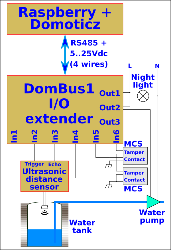
Look at the video showing a Domoticz system with a RS485 network of 12 Creasol DomBus1 managing alarm (50 magnetic contact sensors applied to doors/windows/shutters, some PIRs, some internal and external sirens), several indoor and outdoor lights, measuring water tank level using a ultrasonic sensor, controlling garden watering pump, heat pump using the most energy from photovoltaic, air ventilation, and much more.
Example of house controlled by RS485 bus devices
Telegram channel, to get any support (search DomBus channel in Telegram app)
Creasol DomBusTH
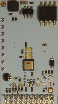
DomBusTH is a small electronic board, 32x17mm, that can fit any blank cover with a 3mm hole in the centre, needed by the thermal/humidity sensor to exchange air with the room and to get the LEDs light out. It can be connected to the Domoticz controller by a RS485 serial bus (4 wires, 2 for 12/24V power supply, and 2 for data at 115200bps).
The electronic board is supplied with a 20cm long, 10 wires, assembly cable with plugin connector, so it's easy to connect the device to pushbuttons, switches, relays, ....
As other DomBus devices, DomBusTH minimizes power consumption, is automatically detected by Domoticz and each port is fully web configurable via Domoticz device description. See below how to change the factory-programmed address of each device, and how to configure each port as digital inputs, analog inputs, digital outputs, dimmer, buzzer, blind, .... by the Domoticz web panel. https://www.creasol.it/DomBusTH
Features
- temperature sensor, factory calibrated with a precisoin of +/- 0.3°C
- relative humidity sensor, factory calibrated with a precison of +/- 2%RH
- 4 wires that can be configured as digital inputs, analog inputs, 1mA digital outputs and buzzer
- 2 open-collector outputs with 40V 50mA capability, that can be used to control external relays, electronic boards inputs with pullup, small LEDs (DomBusTH includes the dimmer function)
- 1 analog input that measure the voltage on bus (but can be configured to measure another external voltage, 30Vdc max, by soldering an additional wire)
- 1 red LED
- 1 green LED
- 1 white LED with 700 mcd luminous intensity
- 7.5-35Vdc power supply (internally regulated by a switching mode power supply circuitry that minimize power consumption and dissipation)
Watch a video showing some functions enabled on DomBusTH !
More information in the Creasol DomBusTH page
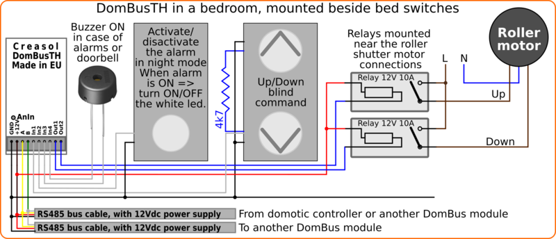
Example: DomBusTH installed beside bed switches, in the bedroom
The following diagram shows how it's possible to use DomBusTH in a bedroom to:
- measure the room temperature and humidity;
- control, by a pushbutton switch, the alarm system and white led: alarm off, short pulse => enable night alarm and turn red Led ON for 2 seconds; alarm on, short pulse => toggle white Led ON/OFF (can be used during the night to go bathroom without wake-up the partner); alarm on, long pulse => disable alarm and turn green Led ON for 2 seconds;
- control, by a double-pushbutton UP/DOWN, the roller shutters: two external relays are needed to drive the roller shutter motor UP/DOWN.
- buzzer alert in case of intrusion detection (alarm) and in case that someone ring the door bell.
Creasol DomBus12
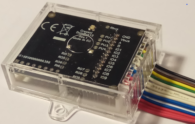
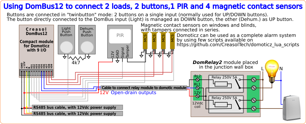
This is a small device 40x30x11mm, with 9 I/Os that can be connected to Domoticz always through the RS485 serial bus. https://www.creasol.it/DomBus12
Features
- 4 configurable I/Os, each one can be set as analog/digital input, twinbutton input, counter, digital output (can be connected to external relay board within relay driver)
- 2 configurable I/Os, each one can be set as open-drain output (to be connected to external relay), analog/digital input, blind output (to be connected to external relay), LED strip dimmer
- 3 configurable I/Os, each one can be set as analog/digital inputs, counter, buzzer outputs, blind outputs (to be connected to external relay board), LED strip dimmer (to be connected to external mosfet)
- 7.5-35Vdc power supply (internally regulated by a switching mode power supply circuitry that minimize power consumption and dissipation)
- low power consumption: less than 10mW
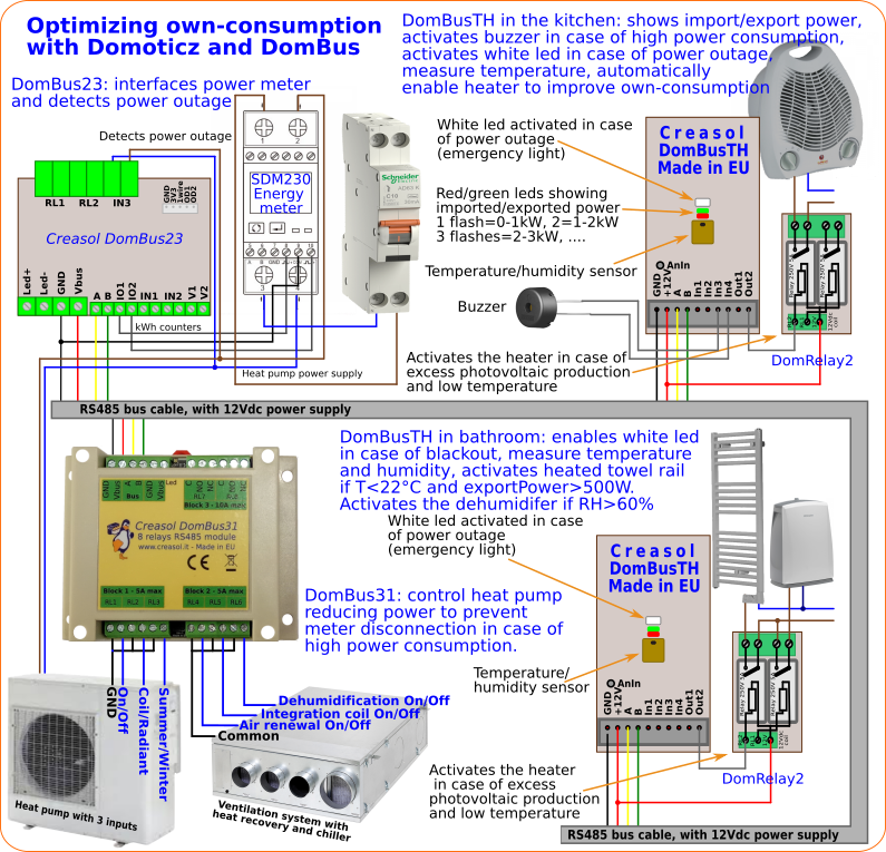
As DomBus12 has 7 inputs that can be used as counters, it's possible to connect two of this inputs to the pulse output of a energy meter to measure the imported and exported power/energy. Similarly, it's possible to connect a gas and water meter.
Also, IO1, IO2, IO3 and IO4 can be connected to NTC thermistors, 10k @25°C, B=3950, that are also available in sealed/waterproof version: NTC are standard temperature sensors, commonly used in chronothermostats.
More info at https://www.creasol.it/CreasolDomBus12
Creasol DomBus23
RS485 module for Domoticz, 74x72x24mm, with several types of I/Os, with only 10mW stand-by power consumption. https://www.creasol.it/DomBus23
Features
- 2x SPST relay outputs, 250Vac 5A, that can be configured in low power mode to minimize power consumption (less than 70mW/relay, instead of 200mW/relay) and in OUT_BLIND mode to drive a roller shutter motor
- 1x mosfet output, 30V 10A max, with both digital and dimmer functions, that can be used to drive led stripe regulating the brightness
- 2x 0-10V analog output (can be used to control other electronic boards with 0-10V input, like dimmers): each one can be configured as open-drain output (available through the optional cable) in case that 0-10V analog output is useless
- 2x I/O lines, each one can be configured as digital input, analog input, twinbutton, counter (for energy gas or water meters), digital output, blind, dimmer (to be connected to external mosfet) and buzzer (piezo buzzer connected to the two lines, in push-pull configuration).
- 2x low voltage AC/DC opto-isolated inputs, 9-40V
- 1x 230V AC opto-isolated input
- 7.5-35Vdc power supply (internally regulated by a switching mode power supply circuitry that minimize power consumption and dissipation)
- low power consumption: 10mW stand-by power
- 115200 bps RS485 bus (max length: 1km)
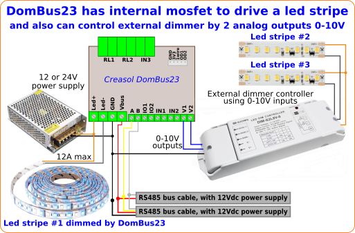
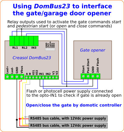
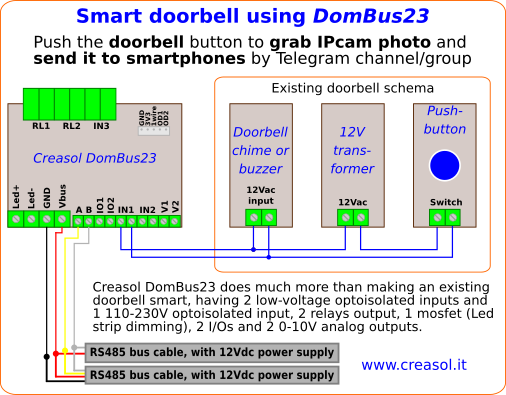
The following schema shows how to convert a simple "analog" doorbell to a smart doorbell, sending picture to Telegram: more info in the Smart Doorbell page.
Creasol DomBus31
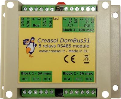
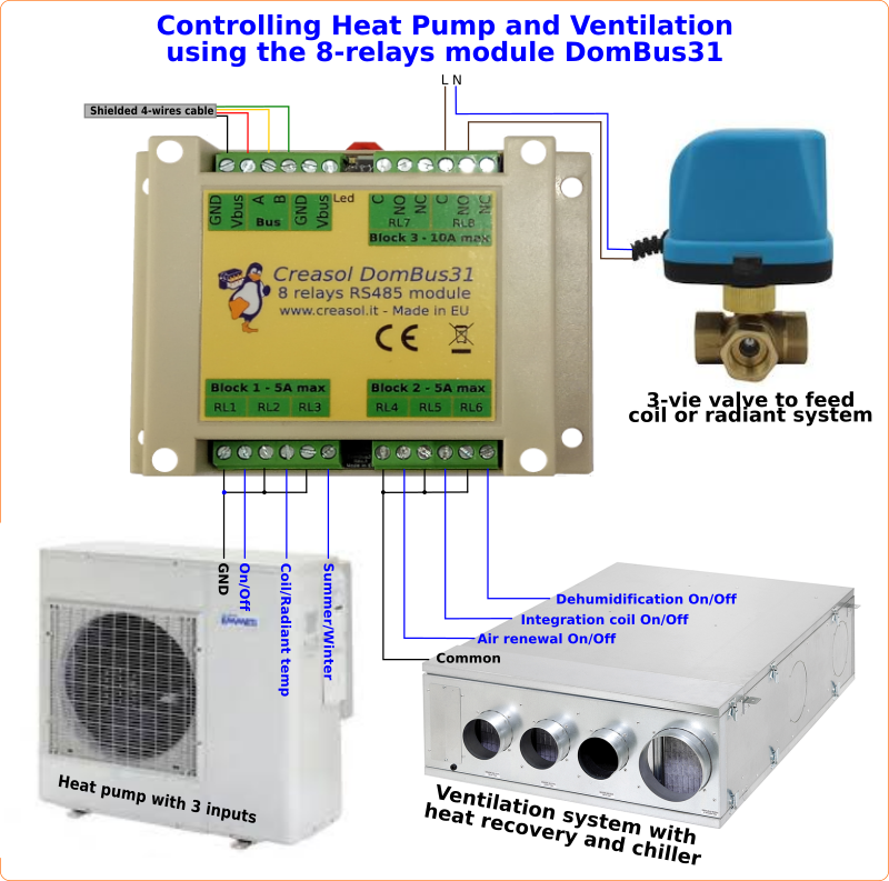
DIN rail module, 115x90x40mm, with 8 relays outputs: 6 relays are SPST (NO output) with 250V 5A max capability, and 2 relays are SPDT (NO and NC outputs) with 10A capability.
It can be connected to the Domoticz controller by a RS485 serial bus (4 wires, 2 for 12/24V power supply, and 2 for data at 115200bps).
As other DomBus devices, DomBus31 provides excellent performance in terms of power optimization: with all 8 relays active (the worst case), the power consumption is only 600mW! With no relay active, it consumes 10mW.
More info at www.creasol.it/CreasolDomBus31
Features
- 6 relay outputs, SPST (normally open contact on screw terminal block) with 250Vac/30Vdc 5A contact (max 30Vdc in case of DC load, 250Vac in case of AC load).
- 2 relay outputs, SPDT (normally open and normally closed contacts on screw terminal block) with 250V 10A contacts.
- Relays are divided in 3 blocks, each block respects the creepage distance from other blocks. Do not mix high and low voltage signals inside the same block!
- 8-35Vdc power supply (internally regulated by a switching mode power supply circuitry that minimize power consumption and dissipation).
- low power consumption: 0.75mA @12V (9mW) stand-by current with all relays OFF, and 41mA @12V (500mW) with all relays ON.
- 115200 bps RS485 bus (max length: 1km).
Heating and cooling system optimizing own-consumption from solar photovoltaic
Creasol DomBus32
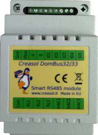
DIN-rail module with 3 relay outputs + 3 AC inputs (110-250V) + 1 common (totally 7 terminal blocks, to have quick connections to device within the same circuit breaker), + 5 configurable I/Os. https://www.creasol.it/DomBus32
Features
- 3 relay outputs, SPST (normally open contact) with 1 common terminal, with 5A capability (max 30Vdc in case of DC load, 250Vac in case of AC load) and overvoltage protection.
- 3 AC optoisolated inputs, 110-250Vac, to detect if voltage is applied.
- 1 common terminal for both relays and AC inputs: in this way it's easier and faster to connect loads (lights, for example) and check if voltage is applied to load or circuit, within a single circuit breaker (do not connect loads that are protected by different circuit breaker, or you have problem with residual current detectors).
- 5 configurable I/O, each one can be connected to pushbutton, switches, double pushbutton, pulsed output counters/meters, buzzer, analog inputs, ...)
- 8-35Vdc power supply (internally regulated by a switching mode power supply circuitry that minimize power consumption and dissipation).
- low power consumption: less than 10mW with all relays OFF, and less than 150mW with all relays ON.
- 115200 bps RS485 bus (max length: 1km).
Creasol DomBus34
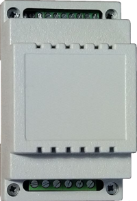
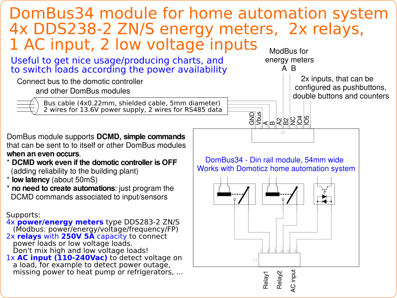
DIN-rail module that can interface up to 4 Modbus power/energy meters DDS238-2 ZN/S, and also includes 2 relay outputs + 1 AC input (110-250V) + 2 configurable low voltage inputs (pushbuttons, analog inputs, NTC thermistors, S0 counters, analog inputs). https://www.creasol.it/DomBus34
Features
- additional RS485 bus to interface from 1 to 4 energy meters, Modbus type, DDS238-2 ZN/S, returning to Domoticz the import and export power/energy, voltage, power factor and frequency.
- 2 relay outputs, SPST (normally open contact), with 5A capability (max 30Vdc in case of DC load, 250Vac in case of AC load) and overvoltage protection.
- 1 AC optoisolated input, 110-250Vac, to detect if voltage is applied.
- 2 configurable low voltage inputs, each one can be connected to pushbutton, switches, double pushbutton, pulsed output counters/meters (S0 meters), analog inputs, NTC 10k temperature sensor, ...)
- 8-35Vdc power supply (internally regulated by a switching mode power supply circuitry that minimize power consumption and dissipation).
- low power consumption: less than 10mW with all relays OFF, and less than 150mW with all relays ON.
- 115200 bps RS485 bus (max length: 1km).
Creasol DomBus36
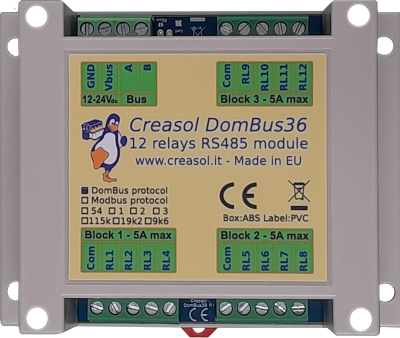
12x relay output modules, with 5A 250V contact capability, protected by overvoltage and high in-rush current, in a small profile DIN-rail enclosure 115x90x40mm.
Relays are grouped in 3 blocks with a single common for each block, for quick wiring. Don't need to make jumpers across terminal blocks to connect line/neutral/gnd to each relay output!
As other DomBus modules, it's available with 2 protocols of your choice:
- DomBus (proprietary multi-master protocol, usable with Domoticz, supporting DCMD commands)
- Modbus RTU (standard, but not optimized)
Very low power consumption: 15mW with relays OFF, only 750mW with all 12 relays ON.
What is DCMD?
DCMD are commands exchanged between modules, activated when a trigger occurrs, like KNX does.
For example, if a short pulse is received on a digital input (connected to a pushbutton switch), activate module X port N; if a long pulse is received, activate module X port M for 120s. If exported power is greater than 1500 activate the boiler resistor (module Y, port N) and deactivate it when exported power goes negative.
All these automations can be specified easily in the Description field of each input (trigger) to activate outputs on the same module or on different DomBus module: in this way it's easy to make automations without the need to use scripts or Blocky.
More info at https://www.creasol.it/DomBus36
Creasol DomBus37
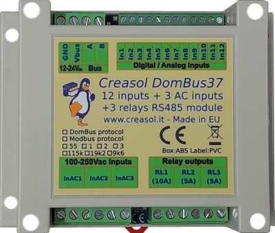
DIN rail module designed for systems using many inputs, like burglar alarm systems, green houses, ...
Features
- 1x 250V 10A relay with N.O. (SPST) connection, configurable in normal or low power mode, blind mode (UP/DOWN motor) and flash mode (connected to a blinker lamp or siren)
- 2x 250V 5A relays with N.O. (SPST) connection, configurable in normal or low power mode, blind mode (UP/DOWN motor) and flash mode (connected to a blinker lamp or siren)
- 12x configurable I/Os, each one can be set as digital input (with internal pullhigh, active low), digital input with pulldown (active high: can accept from +3 to +40V voltage), analog input, twinbutton input (double pushbutton connected to a single module input), counter (energy meter, gas or water meter); an internal 10k pullup that can be activated by PCB jumper (needed for twinbutton and NTC10k sensors)
- 3x 115Vac / 230Vac optoisolated inputs, that can be used as digital input (to detect voltage on appliances, PIRs, and detect power outage) or counter (meter with AC output)
- Optionally, activated by some PCB jumpers, it can supply an alarm siren monitoring the siren voltage, current and status / errors.
- Monitor bus voltage
- The 12 input ports are protected by clamping diodes and can operate between -40V and +40V.
- 9-35Vdc power supply (internally regulated by a high efficiency switching mode power supply circuitry that minimize power consumption and dissipation)
- low power consumption: 12mW normally, 180mW with the 3 relays ON
- 115200 bps RS485 bus (max length: 1km)
- DomBus proprietary protocol, working with Domoticz home automation system, or Modbus RTU standard protocol, working with Node-RED, Home Assistant, OpenHAB, and many other systems.
More info at https://www.creasol.it/DomBus37
Creasol DomBusEVSE
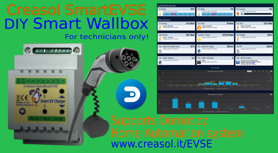
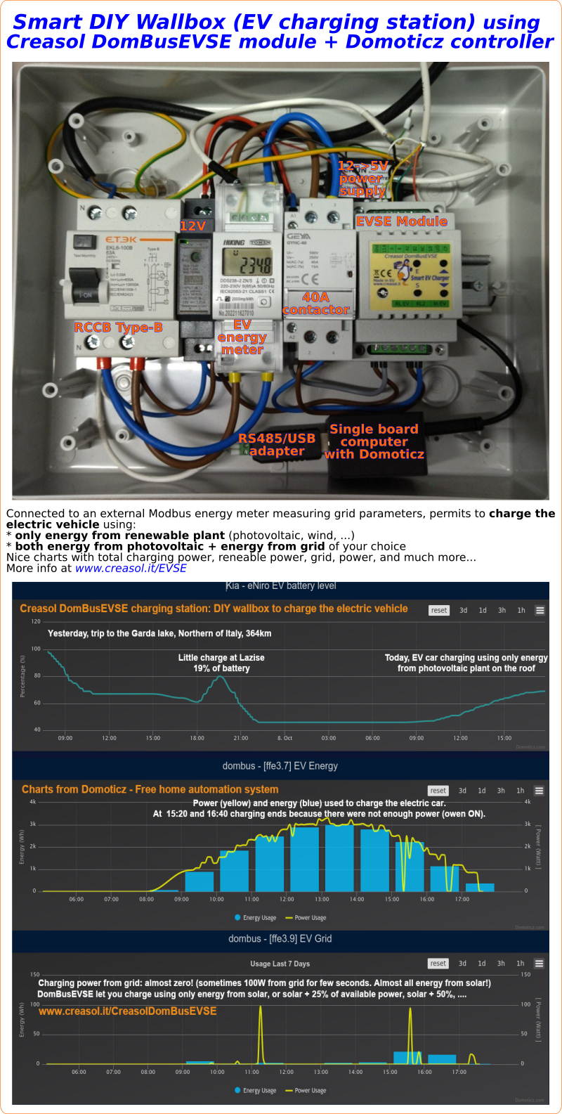
DomBusEVSE is a DIN rail module, designed for Domoticz home automation system, to charge electric vehicles using the standard IEC 62196-2 Mode3 (AC charge, up to 22kW power).
Actually it works only with single-phase charging, but three phase can be easily implemented if requested. It works as stand-alone (without any domotic controller) or in managed mode (charging current controlled by Domoticz).
Mains power supply (230V single-phase, 400V three-phase, ...) is connected to the vehicle through a contactor (relays). Only the Control Pilot wire + earth/ground are connected to the EVSE module. https://www.creasol.it/DomBusEVSE
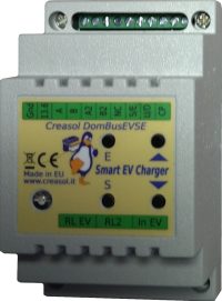
Features

- Manages up to 4 energy meters DDS238-2 ZN/S (single phase), one to measure the charging power/energy, one to measure the power/energy exchanged with the electricity grid. Can also be connected to other 2 energy meters to monitor other loads/circuits, if needed (heat pump, kitchen, ...).
- 5 working modes, that can be configured by the Domoticz UI or by 2 UP/DOWN buttons: OFF: EV charging disabled (led status: red) SOLAR: use only energy from the solar system, assuring that power from grid is 0 (led status: green) 25%: use both solar and grid energy, max 25% of the power availability (for example, with 6kW contract, use max 1500W from grid, + available power from solar) (led status: yellow) 50%: use both solar and grid energy, max 50% of the power availability (for example, with 6kW contract, use max 3kW from grid) (led status: yellow) 75%: use both solar and grid energy, max 75% of the power availability (for example, with 6kW contract, use max 4500W from grid) (led status: yellow) 100%: use both solar and grid energy, max full power (for example, with 6kW contract, use max 6kW) (led status: yellow) MANAGED: charging current set by the domotic controller (by a script, for example) (led status: blue)
- AUTOSTART function: long press on DOWN button (1 second) to stop charging, or the vehicle disconnection set Mode to OFF. When the vehicle is plugged again, the charging mode is automatically restored to the previous charging mode. For example, if charging mode was SOLAR, every time the vehicle is connected the charging mode is set to SOLAR automatically. AUTOSTART can be disabled so when vehicle is plugged the charging process will not start automatically, but will start manually (UP button to change Mode, or by the Web User Interface) or will start based on time (a simple rule on the domotic controller to start and stop charging in the night, for example).
- It displays nice charts with - charging power/energy, that is differentiate into the two following charts - charging power/energy from solar (photovoltaic or other renewable source) - charging power/energy from the electricity grid - charging voltage and power factor - total power/energy from grid - grid voltage, power factor and frequency
- RGB led display current EV state: EV disconnected: 1 flash green EV connected: 2 flashes green EV charging: blue led flashes 1 or more times, indicating the current power (1 flash => less than 1kW, 2 flashes => less than 2kW, ...) EV error: 1 or more red flashes When a new EV mode is selected (from smartphone or using the UP/DOWN button), RGB led shows current mode for 1 second.
How to make a DIY Smart Wallbox (EV charging station) using DomBusEVSE?
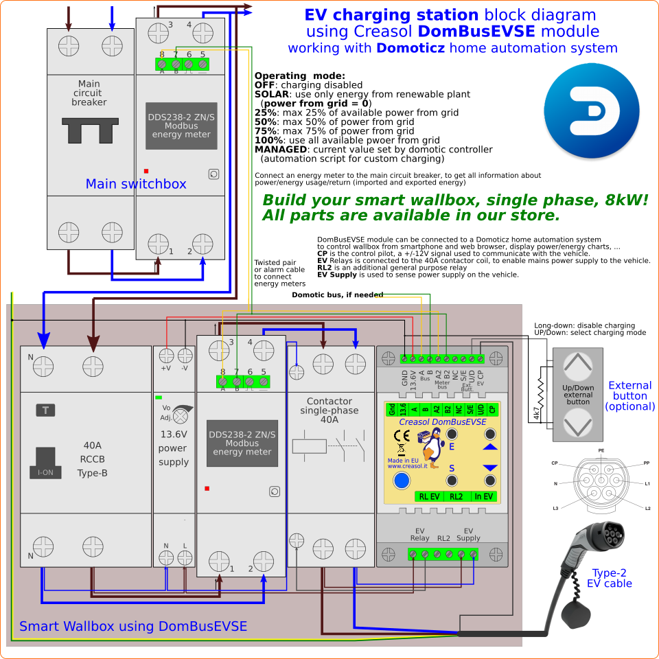
The following diagram shows the connection of the EVSE module to energy meter, contactor, RCD to get a complete smart wallbox, single-phase 230V, sensing the grid power to get the best charging speed preventing overloads and disconnections. Block diagram is available also in PDF format. More info at https://www.creasol.it/EVSE
To build a single-phase wallbox the following parts are needed:
- EVSE module like Creasol DomBusEVSE
- Type-B RCCB that is able to detect differential currents protecting the circuit even if currents are in DC
- One energy meter DDS238-2 ZN/S (Modbus version) to keep account of energy fed to the vehicle, charging power, ... This is a class-1 energy meter so very accurate.
- One 2P 40A contactor to enable / remove mains power supply to the vehicle, disconnecting the vehicle if charging process is OFF
- One energy meter DDS238-2 ZN/S connected to the electricity grid, to detect the import/export power and keep account of energy, voltage, power factor and frequency. This is also good to measure the power and energy consumed by the building, and have nice graphs showing these parameters over the years.
- Type-2 or Type-1 cable to connect the vehicle, and of course some wirings to connect all parts together.
- If 13.6Vdc power supply is missing, a power supply unit 13.6V 15W is needed
- If a DomBus network was not installed, a USB/RS485 adapter is needed to interface the domotic controller
- If no domotic controller was installed, a single board computer like Rock PI-S (for a basic domotic controller with few automations), Raspberry PI4 or similar (more powerful, useful to have a full domotic system with several automations and hundreds of devices) is needed, as like as a 12V to 5V DC/DC converter to supply the single board computer.
As energy meters are factory programmed with Modbus address 1, first connect the energy meter between Type-B RCCB and contactor, and assign address = 2: select Domoticz -> Utility -> M1 Addr device, click on Edit button and write in the Description field ,ADDR=2 then save. Then connect the main energy meter (that measure the power exchanged with the grid) and assign address=2: select Domoticz -> Utility -> M1 Addr device, click on Edit button and write in the Description field ,ADDR=3 then save.
DomBusEVSE has an additional SPST relay output RL2, with 250V 5A capability, that can be optionally used for any purpose, and also supports other 1-2 energy meters that can be used to keep account of energy fed to the heat pump, kitchen, ....)
Creasol DomBus1
DomBus1 was designed to easily expand the number of I/Os of home automation systems using Domoticz software (on Raspberry or other hardware) minimizing the power consumption.

Really plug&play system: extract the plugin on Domoticz, add Creasol DomBus hardware, connect DomBus to Domoticz via RS485 bus, and all I/O of the board will be immediately available in the Switches panel!
DomBus1 can be supplied from 7.5 to 25Vdc, and power consumption is really low: at 12V, for example, 3mA in standby, 9.5mA with 1 relay ON, 16mA with 2 relays ON, and only 23mA with 3 relays ON.
One or multiple DomBus boards can be connected via RS485 bus, so using a 4-wires cable it's possible to implement a network of I/O and sensors where 2 lines are for data and 2 for power supply (normally 12Vdc).
LEDs connected on all inputs, outputs and bus, permit to check the status of the board and found any problem on wire connections: LEDs are enabled by pressing the Prog button and remain active for 60 seconds, then will be OFF until Prog button is pushed again.
The red LED between A and B terminal blocks indicates the serial bus transmission.
Relay outputs are configured for low power mode, consuming less than 30% of the power normally needed by relays, so they can be used for outputs that stay ON for long time (alarm/security signals, lights, ...).
The switching mode power supply, LEDs-enable and low power relay features, lead to a full control of inputs/outputs with an optimized power consumption.
More information in the Creasol DomBus1 page
Hardware installation
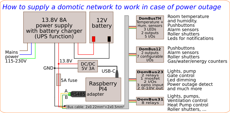
The following schema shows a typical installation using a power supply with 13.8V output and lead-acid battery charger, to get the UPS function. Alternatively, it's possible to use a simple power supply unit, set output voltage to about 13.5V and connect a lead acid battery in parallel (connected through a car fuse).
Also, a 12V to 5V DC/DC converter to supply the RaspberryPI, in case of using Raspberry as domotic controller: in this way it's possible to have a domotic network that works even in case of blackout, feeding DomBus modules, Raspberry, ADSL router, network switches, NVR and IP-cam, ....
In large buildings it's possible to manage more than one bus, each bus connected to a RS485/USB adapter, and connected to the 13.5-13.8V power supply by a protection fuse.
Software installation
You can install the Creasol DomBus plugin from the Python Plugin Manager. This is the simplest solution to install and update the plugin.
Alternatively, from the Raspberry (or linux) shell where Domoticz was installed, type the following commands
if [ ! `which wget` ]; then sudo apt install wget; fi
cd /home/pi/domoticz # or other directory where domoticz is installed
wget -O /tmp/CreasolDomBus.tgz https://codeload.github.com/CreasolTech/CreasolDomBus/tar.gz/master
if [ ! -d plugins/CreasolDomBus ]; then mkdir -p plugins/CreasolDomBus; fi
tar xvzf /tmp/CreasolDomBus.tgz -C plugins/CreasolDomBus --strip=1
service domoticz restart
Then you can find the Creasol DomBus protocol in the Setup -> Hardware panel:
select a name (for example, dombus), select Type Creasol DomBus and enter the serial device used for RS485 bus.
Now you're ready to connect one DomBus device to the RS485 bus, and check the new I/Os in Switches panel or Setup -> Devices
Click on https://www.creasol.it/support/domotics-home-automation-and-diy/132-installing-domoticz-on-raspberry-raspbian if you need to write a microSD with the latest version of Raspbian + Domoticz + backup + firewall , optimized to minimize the number of writes on the microSD flash memory.
